Click on Company Logo to return to Start Page
K2 Engineering, Inc.         Contact us

Specializing in Engineering & Manufacturing Automation since 1996

Steel Pole Analysis and Software Solutions

With experience from 1993 and formed as a separate company in 1996, K2 Engineering, Inc. has specialized in the development of a suite of software-based tools and methods targeted to manufacturers of steel poles and allied equiment, helping them to design and manufacture their products: quicker, lighter in weight, more consistantly, with better documentation, to a variety of applicable codes and standards. Our focus is on helping you automate and streamline your engineering and manufacturing operations as much as possible, freeing your engineers to focus on higher level tasks instead of repetive drudgery, ultimately pushing more and higher-valued product out the door. This all flows to the bottom line where it really counts.

Not sure where to begin? Suspect that you could be doing things better, faster, and more efficiently, but not sure just what is possible? Well, begin by calling or emailing us. The initial consultation is at no cost or obligation to you. Chances are, we'll be able to suggest some course (or courses) of action that you might want to consider, some possibly involving us and some possibly involving third parties. If so, you'll know right away. If we're not the right solution for you, you'll know that right away as well. However, we may be able to refer you to other organizations within our circle of professional contacts which would be a better fit for your needs. (We are quite accustomed to working with third party engineering and manufacturing companies and/or with your in-house personnel). Either way, just the cost of a phone call and a bit of your time.


Finite Element Analysis (FEA) of various steel pole structural components

FEA Model of Vang Plates


  • Most any structual component of a steel pole can be modelled. Just a few possible components are shown above.
  • Some commonly modelled components are: baseplates with or without gussets, framed openings, and arm connections and/or vang plates.
  • Any grade of material can be modelled, if its physical properties are known.
  • Both Static Stress and Eigenvalue (natural frequency and mode shape) analyses are offered.
  • Components can be modelled using corroded or un-corroded thicknesses.
  • Components fabricated from plate are modeled using Plate/Shell elements (where thickness is an input parameter).
  • Bolts are modelled using 3D Beam elements and are joined to adjacent plate elements with Rigid Link elements.
  • Welds are typically assumed to be of a full penetration type and develop the full strength of the joined plates.
  • Optionially, some welds may be modelled using Rigid Link elements, especially when joining thick plates.
  • Boundary conditions at tops and bottoms of tubes feature user-defined translational and rotational stiffnesses.
  • Loads may be applied directly to an element node or to a master node of a 'spider web' of Rigid Link elements joining many nodes.
  • Elements sizes at areas of interest (high stress gradients) are typically 1 inch square or smaller.
  • Element sizes away from areas of interest gradually increase with distance.
  • Most analyses are linear - i.e., do not taken into consideration very large deflections or material yielding.
  • Some more elaborate analyses may consider both geometric and material non-linearities.
  • A variety of stress quantities may be visualized: Von Mises Stress, Principal Stresses, and Maximum Shear Stresses.
  • A variety of deflection quantities may be visualized: X/Y/Z Deflection and Resultant Deflection.
  • Generated reports incude maximum and minimum stresses and deflections and reactions at locations of applied boundary conditions.
  • Generated reports may be customized to your exacting needs.

  • Questions about the intricacies of FEA analysis? Please contact us from some answers!   The initial consutation is free.

    Here are a couple of links that you might want to look at, regarding FEA.

    Wikipedia - Finite Element Method

    What is linear static FEA analysis?

    How can FEA be useful in your development process?

    How to get meaningful and correct results from your finite element model (PDF file)

    Below are some of the pole-specific software tools which K2 Engineering offers:

    (Note: Please call if you have other needs not like anything shown here. K2 Engineering provides customized software solutions.)

    Regarding the product names noted below:

    PLS-Pole™ is a product name and trademark of Powerline Systems, Inc.
    Inventor™ is a product name and trademark of AutoDesk Corporation.
    AutoCAD™ is a product name and trademark of AutoDesk Corporation.
    SolidWorks™ is a product name and trademark of Dassault Systemes, Inc.
    MathCAD™ is a product name and trademark of PTC, Inc.
    EXCEL™ is a product name and trademark of Microsoft Corporation.
    WORD™ is a product name and trademark of Microsoft Corporation.


    PLS-Pole to SolidWorks - a tool to convert PLS-Pole XML-based analysis data into SolidWorks solid models.


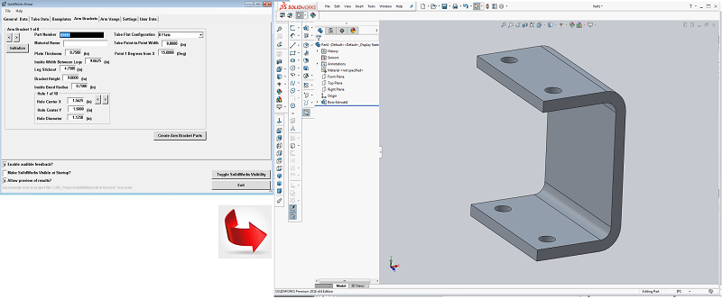
    The creation of a solid model of an arm bracket.


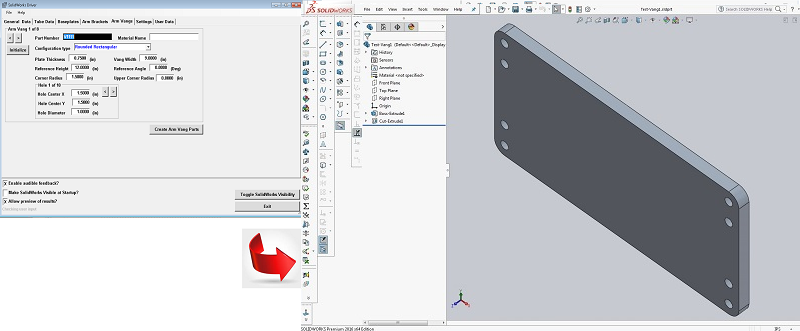
    The creation of a solid model of a vang plate.


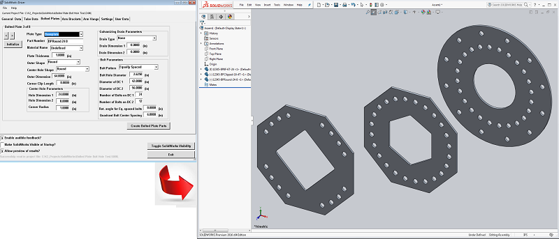
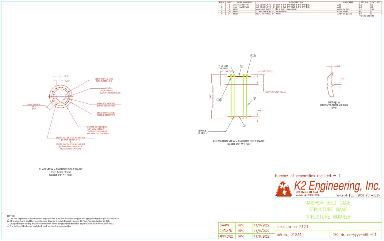
    The creation of a solid model of several baseplates.


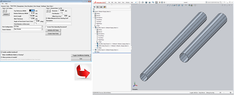
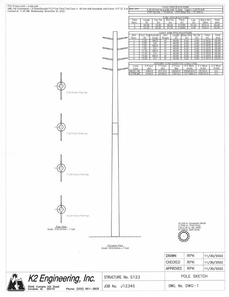
    The creation of a solid model of two pole tubes.

  • Compatible with PLS-Pole Version 8.1 and later.
  • Natively reads PLS-Pole 'postproc'-style XML files. Does NOT require PLS-Pole to be installed.
  • The user's machine must have SolidWorks (Version 2016 or later) installed, however. (All testing was done with SolidWorks 2016.)
  • User-specified SolidWorks Part and Assembly templates (.prtdot and .asmdot files) are used allowing tailoring to user's particular design environment.
  • Note: SolidWorks™ is a trademark and is a licensed product of the Dassault Systemes, Inc.
  • User has option to enter all geometry data by hand, if desired, if a suitable PLS-Pole XML file is not available.
  • All data and settings can be stored and later retrieved from an industry-standard XML-based data file.
  • Tubes having 1 or 2 seams are supported. Locations of seams relative to Longitudinal direction are configurable.
  • Tube pieces (traps) are created from user-specified input including: starting and ending width, wall thickness, axial length, etc.
  • Locations of flats and points relative to seams are configurable.
  • Each tube piece is "mated" to adjoining pieces to create a tube assembly.
  • For Tube assemblies, output consists of a Part (.SLDPRT) document for each piece and an Assembly (.SLDASM) Document for each tube assembly.
  • For Tube Assemblies, input and output file names and locations are configurable.
  • Up to 10 round holes (of any diameter that will fit on the flat) per tube are supported and configurable and may be on any flat.
  • Up to 8 different configurations of flanges and baseplates are supported with a wide variety of outer shapes.
  • For baseplates, quadrant spacing (or equal spacing) of bolt holes is as per the user input for both 1 and 2 bolt circles.
  • For flanges and baseplates, a wide variety of center holes shapes and drain hole schemes are supported.
  • Up to 8 different configurations of Arm Brackets are supported, each with up to 10 user-configured holes.
  • Up to 8 different configurations of Arm Vangs are supported, each with up to 10 user-configured holes.
  • In a multi-pole structure, if importing from PLS-POLE, the desired pole may be selected from a pop-up menu.

  • Note: As it exists now, this program is a Proof-of-Concept to demonstrate how SolidWorks files may be created on-the-fly.
  • Note: K2 Engineering will modify/customize/extend the program and it's output to meet your exacting needs.


  • K2Pole - Pole Analysis via: AASHTO LTS-6 and LRFD-1, EN 40, BS 5649, and ILP PLG 07 (2013)


  • Support for: AASHTO LTS-6 and LRFD-1, EN 40, BS 5649, and ILP PLG 07 (2013).
  • Support for: CSA S6 and ILE TR7 is contemplated as future development.
  • Support for 8, 12, 16, 18, 20, 24, and 36 sided poles as well as Round (where Design Code permits).
  • All standard thicknesses (including gaged) are available in a drop-down box along with an override method for non-standard thicknesses, or metric equivalents.
  • Analysis handled by embedded Finite Element Analysis (FEA) module.
  • P-Delta analysis is available in some load case configurations.
  • Non-linear static stress analysis is available in some load case configurations.
  • Mode 1 - 4 mode shapes and frequencies are calculated using an FEA Eigenvalue analysis.
  • Support for embedded poles (fixity assumed at a user-specified distance below grade).
  • Support for up to 8 Davit Arms, each with up to 5 appurtenances.
  • Support for up to 4 un-reinforced or reinforced openings (Generally as per definitions in EN 40).
  • Support for up to 10 user-defined material property set definitions.
  • Support for accounting of mass of internal cabling (if any).
  • Support for both Metric and British unit sets, both input and output.
  • Support for fatigue analysis (as per Design codes).
  • Support for wind loads from the 8 cardinal directions. Wind load combinations are also supported.
  • Some limited support for seismic equivalent lateral loading. Response Spectrum analysis is currently under development.
  • Pole geometry can be inferred or directly input. Multiple methodologies for specifying/determining lap lengths.
  • Up to 5 point loads can be defined using Equivalent Projected Area and wind parameters or directly specified at any height in any direction.
  • A top mounted appurtenance can be defined. Assumed to be mounted concentric with the pole axis but facing at any azimuth.
  • The wind loads on step bolts may optionially be modeled.
  • All parameters describing head assembly and luminaires at the top of the pole are user specifiable.
  • All significant results parameters (moments, stresses, shears, etc.) can be plotted versus height.
  • All input data and all calculated results are printed out in a nicely formatted manner.
  • Calculated loading parameters (such as drag coefficient) for each pole or arm segment, or appurtenance or point load, may optionially be output in table form.
  • WYSIWYG (What You see Is What You Get) on-screen preview is supported for all printed and plotted output.
  • For ease of use, optionially 'remembers' user settings and configurations from previous sessions.
  • All input data and analysis settings are stored in industry standard, non-proprietary XML format data files.
  • Voluminous text and graphics output capabilities - all user configurable.
  • Support for simplified 3D rendering of pole. (Requires that OpenGL be installed).
  • Text and graphics output may be 'branded' with your company logo and complete contact information.

  • Note: K2 Engineering can modify the program and it's output to meet your exacting needs.

  • Click here to view sample text output of an AASHTO LTS-6 analysis of a pole with davit arms. (British PDF format)
  • Click here to view sample graphics output of an AASHTO LTS-6 analysis of a simple pole. (British PDF format)
  • Click here to view sample text output of an EN 40 analysis of a pole with an opening. (Metric PDF format)
  • Click here to view screen shots of the program in action. (PDF format)
  • Click here to view the Help file for program K2Pole. (PDF format)


  • PLS-Pole to Inventor - a tool to convert PLS-Pole XML-based analysis data into an AutoDesk Inventor 3D model.


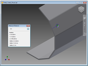
    A round hole being placed in a desired flat.


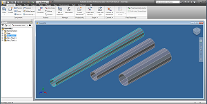
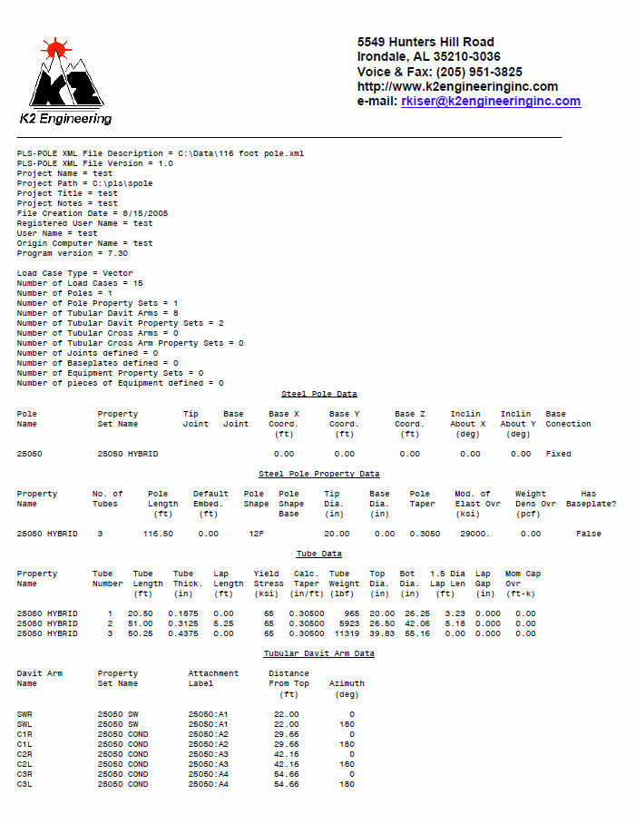
    Three tubes for a pole imported from PLS-Pole.


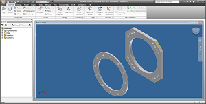
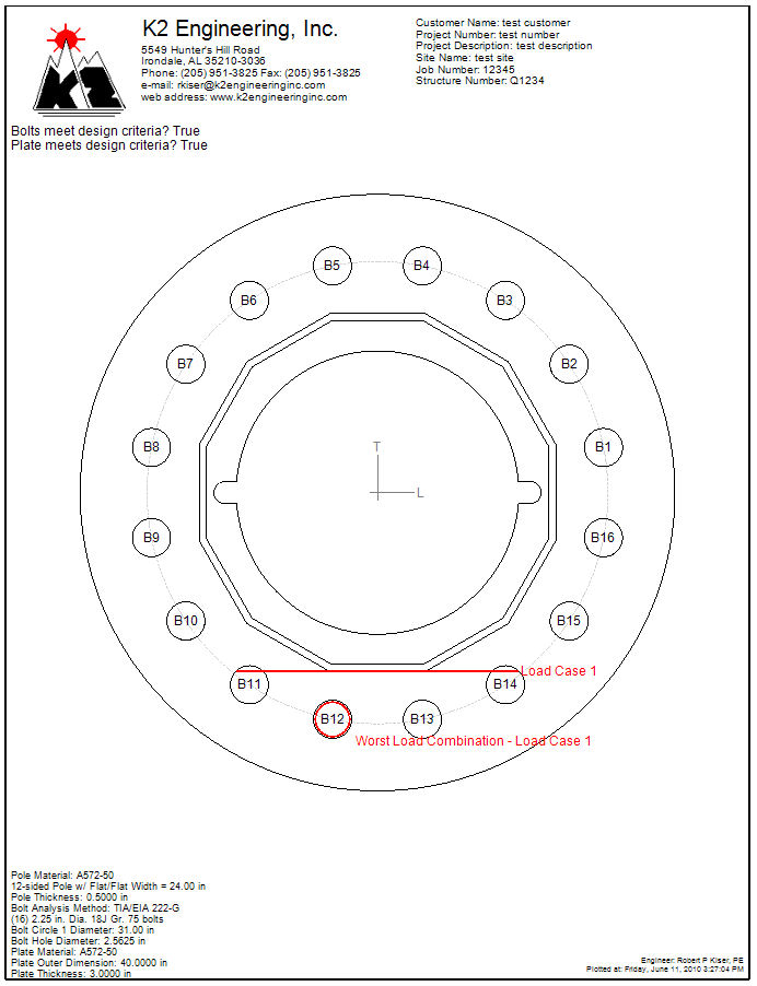
    Two possible configurations of a baseplate.


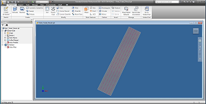
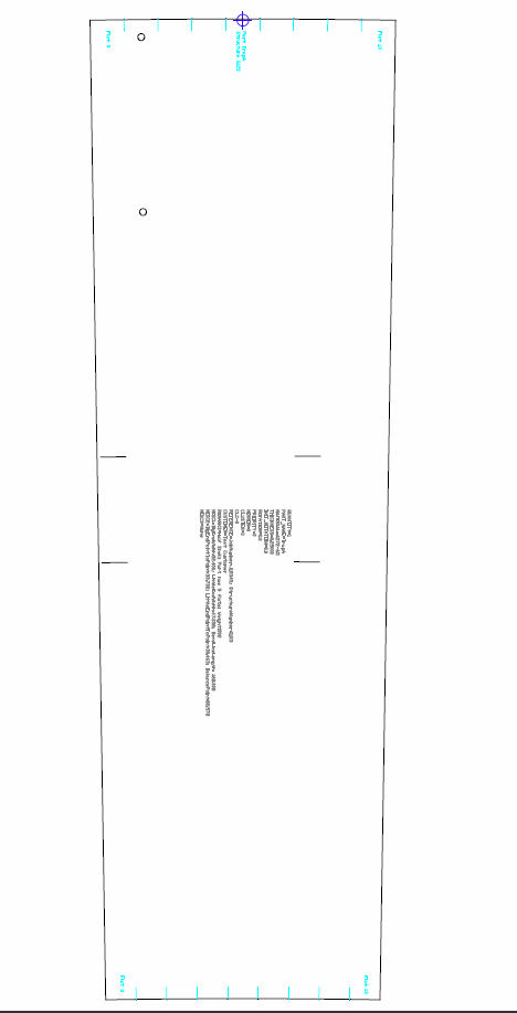
    Tube piece (trap) unfolded into flat pattern.
  • Compatible with PLS-Pole Version 8.1 and later.
  • Natively reads PLS-Pole 'postproc'-style XML files. Does NOT require PLS-Pole to be installed.
  • The user's machine must have AutoDesk Inventor (version 2010 or later) installed, however.
  • Note: AutoDesk™ and Inventor™ are trademarks and licensed products of the AutoDesk Corporation.
  • User has option to enter all geometry data by hand, if desired, if a suitable PLS-Pole XML file is not available.
  • Tubes having 1, 2, 3, or 4 seams are supported. Locations of seams relative to Longitudinal direction are configurable.
  • Tube pieces (traps) are created from a user-customizable part template with custom material properties, bend "K" factor, etc.
  • Flat patterns are automatically computed and included inside each part file.
  • Locations of flats and points relative to seams are configurable.
  • Each tube piece is "mated" to adjoining pieces to create a tube assembly.
  • Output consists of a Part (.IPT) document for each piece and an Assembly (.IAM) Document for each tube assembly.
  • Input and output file names and locations are configurable.
  • Up to 10 round holes (of any diameter that will fit on the flat) per tube are supported and configurable and may be on any flat.
  • Both round and square baseplates (with optional corner clips) are supported.
  • Quadrant spacing of bolt holes is as per the definition inside PLS-Pole.
  • PLS-Pole bolt hole definition may be overridden by user, if desired.
  • PLS-Pole files in metric units are supported. (Output Inventor models will be in British units, however.)
  • Up to 12 poles are supported in each structure, with a maximum of 8 tubes per pole.
  • In a multi-pole structure, the desired pole may be selected from a pop-up menu.

  • Note: As it exists now, this program is a Proof-of-Concept to demonstrate how Inventor files may be created on-the-fly.
  • Note: K2 Engineering will modify/customize/extend the program and it's output to meet your exacting needs.

  • Click here to view sample screen shots of the program in action. (PDF format)
  • Click here to view sample screen shots of Inventor displaying the results. (1 of 2) (PDF format)
  • Click here to view sample screen shots of Inventor displaying the results. (2 of 2) (PDF format)

  • Click here to view a short video of the program in action creating a pole 3D model.
  • Click here to view a short video of the program in action creating a baseplate 3D model.
  • Note: These videos are in .AVI format and will require Windows Media Player or a similar program to view them.
    Note: Video with a higher resolution and frame rate is available upon request.
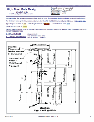